 CZ
CZ
Direct Ignition TCI
No longer for sale!
There is a replacement – MASTER MINI ignition.
The ignition Direct Ignition is ignition with advance controling. It is is developement for the two or four-cycle automobile and motocycle engines. Controlling of advance it possibles in range 0 to 90° in 180 to 20.500RPM. The ignition allows control switching of one or two independent inductors.


Technical Specification
All the functions and optional working ignition regimes can be set by a personal computer. For this reason there is a program Ignition Control that also enables Online visual control of real values of turns, pre-ignition (set-up time). To connect the personal computer through ignition the standard extension cable of USB link should be used.
Analog and digital inputs and outputs allows using more functions, e.g.: advance curve change, block inductors excitation, connectiopn temperature or pressure sensors with possibility change of advance.
Only one digital input can change over the ignition curves. The pre-ignition directing is realized by the conversion of asked pre-ignition curve into schedule of time delays. Depending on actual turns of a motor the individual time delays are chosen from the schedule and via the microprocessor exactly measured and that is how the final effect of set up directing works.
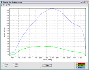
The application Ignition Control newly provides the function of pre-ignition debugging by acceleration brake where the acceleration of motor is watched when repressing its own mass. The acceleration of motor turns is adequate to the twisting moment, which is a ondition.
Main features
- The induction ignition type - TCI
- Supplay voltage range 3,5 to 25V
- Engine working speed 0 to 25.000 rpm
- Working temperature range -40 to 85°C
- Used connectors - Tyco automotive
- Protection cover IP65
- Communication by USB
- Two selectable advance curve
- Selectable exciting inductive coil curve
- Direction capacitive coil e.g. VAPE Z67, Z58, Z69, Z83
- Extended function DI1, DI2, AI1, AI2, DO1, DO2
- Change curves during engine work
- Observation actual state of engine
- Engine work time record
- Acceleration brake
Technical parameters
| Parameters | Range |
| Supply voltage | 3,5 to 25V, (overvoltage protection 33V) |
| Engine working speed | 0 to 25.000 RPM |
| Advance control | 0 to 90° |
| Engine speed for advance control | 180 to 20.500 RPM |
| Working temperature | -40 to 85°C |
| Flash energy | Table, Max., Med., Min., Direction |
| Coil current | max. 15A / 0.085 ohm (MOSFET) |
| Inductor resistance | > 2,5 Ω (12V); > 1,5 Ω (6V) |
| Board voltage | 3,5 to 25V (tol. +-2%) |
| Analog inputs (AI1, AI2) | 0 to 2,5V; 0 to 5V; 0,2 to 2,5k ; > 2,5k |
| Analog / Digital inputs (AI3/DI3, AI4/DI4) | 0 to 5V / 0 to 2V = L; 3 to 20V = H |
| Digital input (DI1, DI2) | 0 to 1V = L, 3 to 20V = H |
| Digital outputs (DO1, DO2) | Open colector (max. 1A, Pull up 1k) |
| Auto. disconnection inductors | Switch off 5 to 120s after stop of engine |
| Signal indicator | Green and Red |
| Communication with PC by USB | yes |
| Protection cover | IP65 |
| Package size | 92x62x25 mm |
| Weight | 250g |
Connector scheme
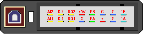
Sign of wires
| SIGN | Description | Range, active level |
| + | Supply voltage | 3,5 to 25V, (protection 33V) |
| G | Ground | 0V |
| 1A | Coil power switch A | Max. 15A / 0.085Ω (MOSFET) |
| 1B | Coil power switch B | < 15A |
| +5V | Sensors supply output +5V | +5V, 100mA |
| PA | Rotating sensor A | -60 až 60V, rise edge 0 -> 1,2V |
| PB | Rotating sensor B | -60 až 60V, rise edge 0 -> 1,2V |
| AI1 | Analog input 1 | 0 to 2,5V; 0 to 5V; 0,2 to 2,5kΩ; > 2,5kΩ |
| AI2 | Analog input 2 | 0 to 2,5V; 0 to 5V; 0,2 to 2,5kΩ; > 2,5kΩ |
| DI1 | Digital input 1 | 0 to 1V = L, 3 to 20V = H |
| DI2 | Digital input 2 | 0 to 1V = L, 3 to 20V = H |
| DO1 | Digital output 1 | Open colector (max. 1A, Pull up 1kΩ) |
| DO2 | Digital output 2 | Open colector (max. 1A, Pull up 1kΩ) |
Installation scheme
Main scheme in variant with two inductors. Input DI1 needn't connect. It is extension function only. For engine with one coils you must connect 1a output only.
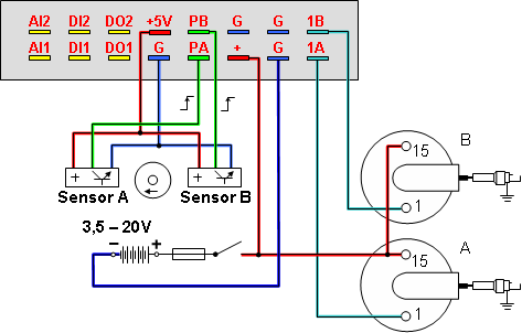
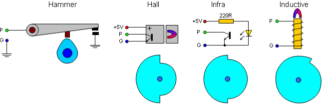
Rotate sensor
It works with extern rotate sensors (Hall, Inductive, Infrared). We are recommending the inductive sensor VAPE, type S01T
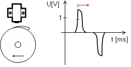
At the base of every signals pulse it generation flash by ignition and coils system.
The advance set up
The last and the most important point in the installation are the proper settings of the ignition to serve all demanded functions perfectly.
First it is necessary to know what maximal pre-ignition advance each engine demands in the first period. This maximal pre-ignition advance must be set in the reading sensor of rotation (e.g. 35°) and also be held as a reference value in the program in a Pre-ignition curve bookmark, item Rotation Reading Sensor. Always the value of pre-ignition set in the sensor must be adequate to the value set in the program. According to this value the conversion of the ignition advance curve is saved in a schedule, mainly the actual truth of On-line visualisation. The value of advance on the rotation reading sensor can be corrected later by comparing the actual value of ignition found out e.g. by a stroboscope to the value of advance set in On-line visualisation.
For easier set up the ignition advance is determined in [mm] in motorbike engines. That is why this program enables the automatic ignition conversion from [mm] to [°]. The ignition conversion window is activated by double click of the mouse in bookmarks Ignition curve and items Rotation reading sensor.
Ignition Control application
The electronic ignition include more functions and optional working ignition regimes can be set by a personal computer. For this reason there is a program Ignition Control that also enables online visual control of real values of turns, pre-ignition (set-up time). The application works under the Windows 95 or higher. It requires 4MB of empty space in hard disc. The minimum PC configuration is Pentium 166MHz, 32MB RAM is accurate.
Ignition Control Program is divided into four individual parts:
- Online visualisation
- Ignition advance curve
- Extended functions
- Sensor calibration
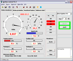
Online visualisation showing this parameters
- Engine RPM
- Engine advance
- Network voltage (Board voltage)
- Digital inputs (Pa, Pb, DI1, DI2)
- Digital outputs (DO1, DO2)
- Analog inputs (AI1, AI2, AI3, AI4)
To run visualization it is always necessary to connect the computer with the ignition by a serial extended cable, to open the communication port and to run the visualization by pressing the button Start. In case that after pressing the button Start the real data do not display please control the connection of communication cable, the number of the used communication port and the voltage of the ignition.
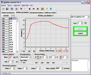
The ignition advance curve
The basic character of the ignition is the directing the ignition advance according to real turns of the engine. To set ignition advance directing characteristics there is Ignition advance curve bookmark.
Flash energy
To optimize the type of the inductors and its excitation there is Flash energy button. It is necessary to set medium or minimum excitation that will protect the inductors against the over excitation and their over heating when using inductors with resistance lower than 4ohm (min 2,5 ohm). If using the inductors with the resistance higher than 4ohm there is medium or maximal excitation settings. The settings of Flash energy directing that directs exciting according to values of board voltage is the compromise of the excitation inductors.
| Board voltage | Control flash energy |
| > 9V | Maximum |
| 9V - 11,5V | Medium |
| < 11,5V / < 3300RPM | Minimum |
| < 11,5V / 3300 - 6500RPM | Medium |
| < 11,5V / > 6500RPM | Maximum |
It possible configuration coil current by exciting curve or table. You can set exciting from 20 to 95% per a round.
Pre-defined process of coil exciting
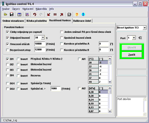
Extended functions
To increase safety of running and also for extended ignition advance curve settings possibilities there are extended functions. It is a file of digital inputs DI1 up to DI4, outputs DO1, DO2 and analogical inputs AI1 up to AI4. The functions of individual extending inputs and outputs can be permitted or inverted.
- Power down - 5 up to 120s
Permitting to automatic coil excitation switch-off after asked time of 5 up to 120s passed. It prevents from the coil damage by permanent exciting current.
- RPM limit -1000 up to 25000 turns/min
Permitting turn limit function causes regular interrupting of the coil excitation after exceeding asked turn limits.
- RPM stop - 1000 up to 28000 turns /min
Exceeding asked turns causes full interruption of excitation. It will be renewed when stopping the engine.
- DI1 - Switch Curve 1/ Curve 2
It enables easy ignition advance curve switch-over whenever the engine is running. If the function is not active Curve 1 is used.
- DI2 - Blocked run
It provides the immediate possibility of blocking the engine starting up or running.
- DI3 - Blocked run
It provides the immediate possibility of blocking the engine starting up or running.
- DI4 - Reserve
The reserved input for the future use.
- DO1 - Switch [x1/min]
Output to the speed counter.
- DO2 - Switch RPM [1/min]> Asked turns
Output switched according to asked number of turns.
- AI1, AI2 - Correction of advance
The base advance curve is functionality of RPM. It possible corection this curve with <-15°;+15°> range by AI1 and AI2 analog input.
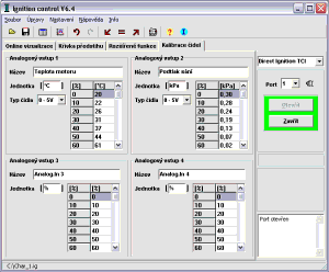
Example of calibration sensors in bookmark Sensors Calibration where sensor works in 0-5V range.
0,0V (0%) = 20°C
0,5V (10%) = 22°C
1,0V (20%) = 26°C
1,5V (30%) = 31°C
2,0V (40%) = 37°C
2,5V (50%) = 44°C
The sample of correction is in bookmark Extended function where is advance decrease about 4° for 22°C engine temperature.
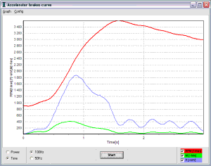
Acceleration brake
There is a new function in Online visualization. It is Acceleration brake that realizes fast 5 second engine record with the calculation of the turn derivation (acceleration). It proportionately responds to torsional moment.
Measure process
- Check the Engine Turn Limits settings before use
- Leave the engine run idly and get ready for its acceleration
- Press Start button
- Wait exactly 1 second to run the record
- Running of the record for 5 seconds
- End up the record and read the measured values of turns from ignition
- Display and conversion the measured values to the graph
Why you should use the electronic ignition
The electronics ignition allows very exactly direction of advance. This provide more of engine power in wide rande RPM. The ignition allows very easy engine to start (optimal advance), more power (high energy of flash) and with the rules of economy driving then decrease of fuel consume. The ignition is work in guaranteed voltage range from 3,5V to 25V.