 CZ
CZ
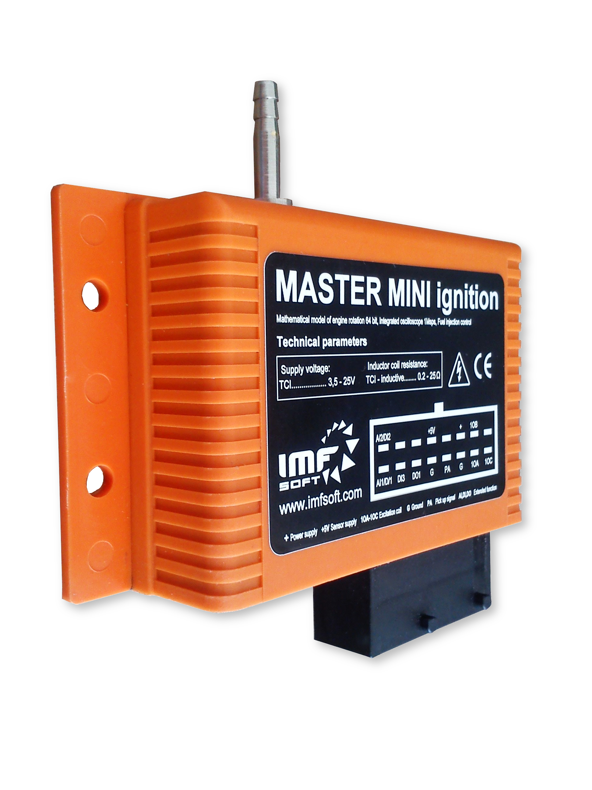
MASTER MINI ignition TCI
Cannot be ordered, due to low interest we no longer produce. The replacement can be a unit in an aluminum case MASTER 4TCI.


Technical Specification
No longer in sale!
Possible replacement MASTER 4TCI.
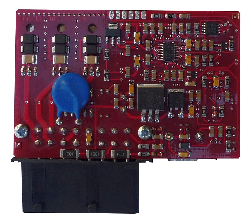
The unit MASTER ignition has been functionally designed in order to control advance or injection of combustion engines ranging from one to six cylinders, with whatever configuration of scanned teeth, types of sensors and features like 5D maps of advance and injection control, integrated pressure sensor, temperature, tachometer output, strobe lamp, charging control, engine speed and turbo preassure PID regulation, control switching on of fuel pump. Unit MINI contains only 3 TCI outputs.
The list of features mentioned above determines MASTER ignition to be used either for a service or tunning replacement of conventional motorcycle or automobile ECU units, usable for ignition or injection coil control. The integrated redundancy of sensing, together with other key features makes Master ignition very suitable for marine and aviation applications, moreover, thanks to the wide range of operating revolutions can be also used for turbines.
The function of MASTER ignition relies on FPGA technology, which provides digital-analog conversion of sensor signal, as well as its evaluation and calculation of the mathematical model of the real rotation. Simultaneously, it deals with other operations i.e. redundancy sensing, total control of CDI converter, advanced features and signal records. FPGA technology is interesting not only for its high operating performance but particularly for its accuracy, which in principle microprocessor-based systems cannot achieve.
MINI - available units
TCI = output for inductive ignition coils or injection
- MASTER MINI ignition 3xTCI (3× outputs TCI; 3,5V up to 25V)
- MASTER MINI ignition 3xTCI P sensor (3× outputs TCI; 3,5V up to 25V and integrated Pressure sensor - brought out from the housing by a nipple)
Main Features
- The power supply range of 3,5 to 25 V
- Working speed from 0 to 120 000 rpm
- Operating temperature -40 to 85 °C
- Based on FPGA technology and microprocessor support
- Mathematical model of the real engine rotation, 64bit
- Adjustable pick up sensing levels, A/D conversion of signals, ± 25.5 V, 1Msps
- Angular maps of teeth, the voltage levels for different speeds, filters capture
- Customizing the input type sensor: Induction, Hall, Optical, Hammer
- Redundancy of sensing and other integrated elements
- Advance and Injection control – optional 5D map of ±360° and 0 to 60ms
- Integrated oscilloscope, runtime visualisation of pick up and switching, ± 25.5 V, 1Msps
- Outputs TCI – MOSFET
- Advanced functions – temperature, vacuum, vibration, tachometer, charging
- User configuration by PC – while in operation with possibility of status visualization
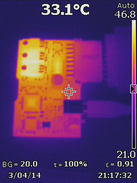
- Measurement of voltage, temperature and load of converters
- Records – long-term and common, engine hours
- Convenient Firmware Upgrade – regulary and easy updates via the website
- Rapid diagnosis function using LED
Technical parameters
| Parameters | Range |
| Supply voltage | TCI … 3,5V – 25V |
| Current Consumption | TCI … < 100mA |
| Working speed (range management) | 0 – 120 000 rpm (0.1 – 65 000 rpm) |
| Working temperature | -40 – 85°C |
| Input mode (PA) | ±25.5V, ±0.1V – ±50V, sampling 1Msps |
| Maps advance [1]…[8] | ±360°, 8 × 1024 pts, (0.1–65 000 rpm) |
| Maps injection [1]…[8] | 0–30ms, 8 × 1024 pts, (0.1–65 000 rpm) |
| Switching coil (1OA, 1OB, 1OC) 3xTCI | TCI … MOSFET automotive 25A/300V |
| Digital inputs (DI1–DI3) | 0 – 2V = L, 3 – 16V = H (Pull up 1kΩ) |
| Analog inputs (AI1,AI2) | AI1, AI2 … 0–5V |
| Digital outputs (DO1) | MOSFET 5A/100V (Pull up 1kΩ) |
| Measurement of voltage (power supply) | 7 – 50V (tol. ±2%) |
| Temperature measurement (inside housing) | -40 – 125°C (tol. ±2°C) |
| Resistance of primary winding coils* | TCI – Induction, resistance 0.2–25Ω (Pull up 1kΩ) TCI – Injection, resistance 0.2–25Ω (Pull up 1kΩ |
| Memory record | 8kB RAM, 8MB FLASH |
| Status indication by LED | Blue, Red |
| User Configuration - USB | Freeware software MASTER control |
| Protection cover | IP65 |
| Package size | 120x67x25 mm |
| Weight | 225 g |
* measured between terminals 1 (switching) and G (ground) for capacitive coil or 1 and 15 (supply) induction
Connector plugging
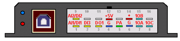
| Marking | Meaning | Range, Active Level |
|---|---|---|
| + | Voltage suply | 3,5V – 25V |
| G | Earthing power, sensors | 0V |
|
1OA-1OC |
Switching coils A-C or user outputs |
TCI* – Inductive, resistance 0.5 – 5.0Ω (Pull up 1kΩ) TCI* – Injection, resistance 0.5 – 5.0Ω (Pull up 1kΩ) |
| +5V | Power sensors output | +5V, 100mA |
| PA | Rotation sensor A | ±25.5V, minimum 0.1V, sampling 1Msps |
|
AI1, AI2 DI1, DI2, DI3 |
Analog input AI1,AI2 Digital input DI1,2,3 |
AI1,AI2: 0–5V; DI2: 0–16V; DI1,DI3: 0–16V (Pull up 10kΩ) |
| DO1 | Digital output 1 | MOSFET 1A/100V (Pull up 1kΩ) |
* TCI output - other use (switching injectors, fuel pump, a stroboscope, tachometer etc.)
Important notification:
MINI MASTER unit compared with MASTER standard (in aluminum case) is reduced by these signals AI3, AI4, D4, PB, 1OD. All software functions including injection support are preserved. In MASTER Control application is only necessary to choose HARDWARE VERSION → V7.X.
Preview of application
Online visualisation
This is an operational display of function and status of ignition unit MASTER. In order to have functional display it is necessary to have USB connection and switch power supply on.
Visualised data
- Speed (rpm) and advance of engine [°]
- Sensor voltage PA, PB [V]
- Power supply [V] and Temperature [°]
- Converter CDI – Voltage [V], pulsed current [A] and load [%]
- Signals 1OA - 1OH, DI1, DI2, DO1, DO2, AI1, AI2, PA, PB
- Engine hours [s]

Maps of advance
Maps provide a fast tool to display and model individual curves in advance [1] – [8] in full angle range ±360°. The given figure influences the moment of output switch from 1OA to 1OH. By using digital (DI1, DI2) or analogue outputs AI1, AI2, PA, PB) it is possible to operationally switch among the maps.
Modelling tools:
- Editor maps in advance – quick draw of maps according to specified points
- Mouse modelling – direct editing of maps is possible by mouse movement
- Map shifting – whole map shifting or selected parts only
- Copying – copies of maps one to another of your choice
- Table – direct entry of specific points into table
- Filter – in-progress filtration, rounding the edges of maps

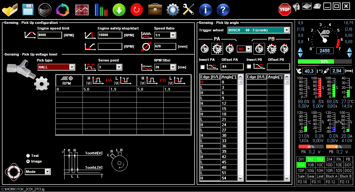
Sensing configuration
Configuring the sensing of engine rotation is the key part of ignition unit MASTER ignition. Within its setting it is possible to select Pick Up voltage sensing level and adapt this level for more range of engine speed. There are other settings to be selected such as filter setting, angles of Trigger Wheel teeth maps or alternatively second level of voltage for synchronisation.
Pick Up voltage sensing level and Trigger Wheel teeth map are predefined for many application Eg. BOSCH 60-2, BOSCH 36-2, BOSCH 2+1, BMW 36-1, FORD 36-1, SUZUKI 24-2, YAMAHA 16-2, HARLEY 32-2.
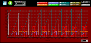
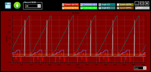
Oscilloscopic record
Oscilloscopic record is used in order to graphically visualise measured and calculated data. This helps to quickly evaluate the proper and accurate function of ignition unit MASTER. It can thus evaluate the correctness of voltage sensing, counting teeth of mathematic model of the real rotation and angels of closing of output coils.
An example to be given; curve angle of engine displacement must be regularly and horizontally increased from 0 to 360°. If there is any change of steepness in the curve or the angle is shorten, the problem is to be found either in wrong angle set up, number of teeth, the type of synchronisation or unsuitable voltage for sensing.
Visualised data:
- Rotation sensor voltage, PA, PB [V]
- Tooth index of sensed blade, Tooth index A-B [-]
- Engine displacement angle, Angle A-B [°]
- Engine revolutions, Revolutions A-B [%]
- Outputs closing 1OA-1OH [-]
Videos
Software tutorial
Reference videos
MINI MASTER unit compared with MASTER standard (in aluminum case) is reduced by these signals AI3, AI4, D4, PB, 1OD. All software functions including injection support are preserved. In MASTER Control application is only necessary to choose HARDWARE VERSION → V7.X. Please note: Documentation at the bottom is uniform for all version of MASTER units!
USB flash disk with all documentation and PC application:
If you buy a flash drive at the very bottom in Recommended accessories (here), we will upload all the necessary documentation and software to it.
Otherwise, these files are also freely downloadable below.
Application Software
| Name | Date | File |
|---|---|---|
| PC application V8.46 MASTER control – [zip, 976 kB] | 04.07.2025 | Download |
| USBdriver_v2.12.36.20 [zip, 1591 kB] | 30.06.2026 | Download |
| *.ig file examples – [zip, 2,46 MB] | 03.06.2024 | Download |
| Ignore Serial Number Utility (Windows XP) [zip, 64 kB] | 02.11.2014 | Download |
| Example of DATALOGGER file [csv, 234 kB] | 06.02.2015 | Download |
Recommended Accessories
-
Inductive ignition coil I03 (TCI)
Common applications, 1x Output, Resistance = 1.5Ω

-
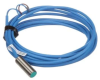
NAMUR sensor N08
Sensing engine rotation from zero speed, only two wires
-
Inductive coil I06 (TCI)
Common applications, 2x Output, Resistance = 0.6 Ω

-
USB flash disk
USB flash disk - uploaded with SW and documentation
